ER9 electric trainset
This article needs additional citations for verification. (August 2017) |
| ER9 | |
|---|---|
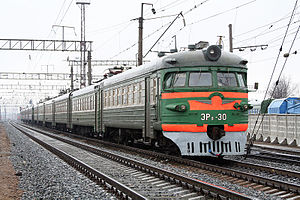
 ER9-30 at Murom, Gorkovskaya Railway | |
| Manufacturer | Rīgas Vagonbūves Rūpnīca |
| Entered service | 1962- |
| Specifications | |
| Electric system(s) | 25 kV 50 Hz AC Catenary |
| Current collector(s) | Pantograph |
| Coupling system | SA3 |
| Track gauge | 1,520 mm (4 ft 11+27⁄32 in) Russian gauge 1,435 mm (4 ft 8+1⁄2 in) standard gauge Bulgarian State Railways |
For servicing suburban commuter lines, electrified on 25 kV, AC, the Railcar Manufacturing Plant of Riga produced ER9, then ER9P and other modifications of electric trainsets in the 1962-2002 period. The mass production of these trains had begun in 1964.
Railcar types
[edit]Three types of cars were manufactured for these trains, which were motor, trailer, and cab-trailer. The minimal quantity of cars is four (2 motor & 2 cab-trailer cars). The maximal quantity was twelve (6 motor cars, 4 trailers, and 2 cab-trailers.) The trains could be controlled and/or operated only from cab cars.
Design and construction
[edit]Railcar bodies
[edit]The railcar bodies utilise a frameless construction similar to the ER2 series trainsets, with a number of modifications due to the different equipment arrangement, such as AC transformers and rectifiers. The car entrances are fitted for both high and low platforms. Like most Soviet rollingstock, the cars have SA-3 automatic couplers.
The bodies are supported by two twin-axle bogies. The bogie frames are an H-shaped fully welded construction. Trainsets constructed up to ER9p-125 have N. E. Galakhov's elliptical amortizers in their central suspensions. Bogie frames are supported by 8 cylindrical springs installed in a coat of axle box balancers. The static deformation of amortizer is 105 mm. Starting with ER9p-126 trainset (1966), the trolleys are supported on axles box through four sets of cylindrical springs, placed in two rows. The hydraulic amortizers are placed in the central suspension, like the ER2 motor cars dating from 1966 to 1975. The static deformation remained the same (105 mm). The diameter of motor car wheels is 1050 mm, and of trailer car wheels is 950 mm.
Electric traction motors
[edit]Electric traction engines are installed on bogie frames, as in ER2 motor cars. The engine's shaft is connected with the minor gear train using a jaw clutch. The speed reduction couple's body is anchored on a pair of wheels through friction reducer made of rolls. From the side of minor gear train, the speed reduction couple is suspended from the trolley's frame.
- Traction Motors specifications
Unit: Electric Traction Engine (RT-51D) Installed: On motor cars Voltage: 825 V, directly from rectifiers. Power: 180 kW, 240 A (in case of 92.5% excitement) 200 kW, 266 A (in case of 32% excitement)
Rotational frequency: 645 rpm (in case of 92.5% excitement) 1140 rpm (in case of 32% excitement)
In case of pulse current, and 32% excitement the hourly power is 182 kW. The rotational frequency 2080 rpm.
Mass of Unit: 2000 kg The motors are connected in series of two. These series are connected in parallel, and connected to the rectifier through general smoothing reactor. Besides high (92%) and low (32.5%) excitement levels, there is a medium level (53.5%)
Transmission
[edit]The transmission is one way, rigid, and straight-cogged. The ratio is 23:73 (1:3.17) Two braking cylinders are installed on every motor car's trolley. Brake shoes depress the wheel from both sides. The brakes feature electro-pneumatic control.
Transformer
[edit]Unit: OCR-1000/25 transformer Suspended: Under the body of a motor car Manufactured: At the Electric Technology plant of Tallinn The transformer has a core type, and is cooled by oil.
Composed on 4 coils: Primary, for 25 kV (normal power 965,000 volt-amperes), Traction coil: 7 outlets with regulating electrodes. Output voltage - 2208 V (During neutral position)[citation needed] Normal Current 350 amperes Hourly Current 530 amperes
- Heating coil
power: 100 kV·A output Voltage: 628 V Supplementary coil power: 92 kV·A voltage: 220 V. Transformer's mass is 3122 kg.
Pneumatic switch/circuit breaker
[edit]Unit: The main pneumatic switch (VOV25-4) Mounted: On the roof of motor car Purpose: to protect the high voltage circuits from short circuit currents and overloading. Manufactured by: High Voltage equipment plant of Nalchik.
Unit: UVP-1 Rectifier. Mounted: Under the body of motor car Features: Bridge scheme
Rectifying circuits
[edit]The unit has 30 VK2-200-6B rectifiers. Every bridge's arm has 3 parallel circuits, consisting of 10 rectifiers connected in series. The branchings have 3 parallel circuits, with 2 rectifiers connected in series. For even distribution of reverse voltage in serial circuits, the active resistors are connected in parallel with rectifiers in non-conducting period. The connection of rectifiers with same potential is realized by resistors.
- In motor cars so called "rectifier transfer," from one step of voltage to other is done. This feature allowed to exclude a division reactor from design. For this purpose rectifier branchings are connected in rectifier groups, which form a bridge arms. Every arm has 3 circuits connected in parallel, each of them has 4 rectifiers connected in series. that's why the total number of rectifiers in motor cars is 144. The normal value of rectified voltage is 1650 V, Current is 600 amperes. The unit weighs 580 kg.
Controlling train speed
[edit]Unit: KSP - 6B Controller Purpose: Regulating the voltage on Electric traction Engines' clamps, as well as their excitement level. Composition: 18 contactors and leads. The system is developed by Professor L. M. Reshetov. The unit has 20 working positions.
Position 1: Maneuvering
[edit]The voltage from one traction coil segment follows to traction engines' clamps through starting resistor, and rectifier. The engines are working in high excitement mode.
Position 2
[edit]The circuit is the same, excluding the starting resistor.
Subsequent positions (3 to 16)
[edit]The voltage on motor clamps is increased, due to the serial connection of load to the traction coil output.
Position 17: The excitement level is brought down to 53.5%. Position 18: The same working mode as position 17. Position 19: The excitement level is brought down to 32%.
The main controller is controlled by Engineer's controller (1KU - 023). The unit has two handles. They are: Reversive - features Reverse, Drive, and Neutral positions. Main - features neutral, maneuvering, and 4 working positions.
Traction engines and most of electrical devices are manufactured by the Electric Equipment plant of Riga.
Unit: Phase Splitters Placed: Under the body of Motor cars. Purpose: Converts single phase 220 V Current into 3 phase. The produced current serves for powering various supplementary machines.
Unit: Fan wheel. Placed: On splitter's rotor(?). Purpose: Cooling rectifiers, reactors, and transformers. The rotational frequency of the splitter is 1495 rpm.
Unit: Motor - Compressor. Composition: LOSV-72-6 Electric Motor, with EK1-V or EK-1P compressor. Performance 0.7, 0.6 and m3/min. Location: Under the body of attached and cab cars.
Unit: Alkaline, accumulator battery (90KN-55) Normal Voltage: 110 V. Charged by 220 V coil of the transformer, through silicon rectifier. The stabilized is in use for supporting the voltage. Location: Under the body of attached and cab cars.
The construction speed of the trainset is 130 km/h. Calculated acceleration up to 60 km /h is 0.8 m/s^2.
Weights: Motor Car - 59,000 kg 108 Seats; Attached Car - 37,000 kg 110 Seats; Cab Car - 39,000 kg 88 Seats;
Modifications to layout and construction
[edit]In process of manufacturing, a lot of changes were introduced in ER9p construction. Starting with ER9p-125 train, jaw clutch drive clutch is changed by rigid roll. Electric engines rotor rod is connected with minor cog wheel using rubber cord shell (like in ER2 motor cars)
- Starting with ER9p-230 trainset (1969), the UVP-1 rectifying unit is changed by UVP-3. It features 84 VKLD-200-8B avalanche rectifiers. Every bridge's arm has 3 parallel circuits, consisting of 6 rectifiers connected in series. The branchings have 3 parallel circuits, with 2 rectifiers connected in series. the connection resistors are absent in UVP-3, as well as devices reacting to rectifier fan-out. (?)
- Starting with ER9p-345 (1974) trainset Cab Trailers were released with more flat head. (As in ER2 electric trainsets trains numbered 1028 and up).
Modified versions of ER9
[edit]ER9P
[edit]Produced since 1961. In difference of ER9, the rectifiers were placed in car bodies not in passenger space compartments.
ER9M
[edit]Produced since 1976. In difference of ER9P, ER9M trainsets have high voltage compartment in their motor cars, where a high voltage bus is located. In ER9/ER9P it was done through the wall.
- Cushioned seats are installed instead of wooden ones. (Similarly with ER2 electric trainsets numbered 1112 and up.
ER9E
[edit]Produced since 1981. Differs from ER9M by natural air cooling of rectifiers.
ER9T
[edit]Produced since 1988 till the end of ER9 manufacturing by the plant in Riga. This modification has modernized bogies, traction engines and rheostatic brakes.
-
ER9P-276 near Berdanosovka, (Lipetsk Oblast), Russia
-
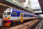
ER9M-390-01 - railway station in Vilnius, Lithuania
-
Interior of the ER9M in Lithuania
-
ER9M-513 train station of Nizhyn, Ukraine
-
ER9E-591 at Vysochino, Bataysk, Russia
-
ER9T-683 near Saratov, Russia
-
ЕР9p-361 at Tarasa Shevchenka Station, Ukraine
-
ER9M-501 at Kyiv-Pasazhyrskyi station, Ukraine
ER25 contract, for Bulgaria
[edit]Bulgaria Railways ordered ER25 trainsets from Railcar Manufacturing plant of Riga. The plant projected rheostatic braking system for these trains. ER9p-101 electric trainset was equipped with such a brake. This train was tested on experimental circle track of CNII of Railroad Ministry. The rheostatic braking was in use for lowering speed from 130 km/h down to 50 km/h. Then regular electro-pneumatic braking was in use. After that, the electric trainset entered Gorky Depot for a permanent use. It worked on common schedule with other ER9p electric trainsets.
In 1974 Tallinn Electrotechnical plant manufactured experimental UVP-5 rectifying units. They featured tablet avalanche rectifiers (12th class) with natural air cooling. One of these units was mounted in ER9P-32304 motor car, which were in use by Gorky Railroad.
See also
[edit]- The Museum of the Moscow Railway, at Paveletsky Rail Terminal, Moscow
- Rizhsky Rail Terminal, Home of the Moscow Railway Museum
- Varshavsky Rail Terminal, St.Petersburg, Home of the Central Museum of Railway Transport, Russian Federation
- History of rail transport in Russia
References
[edit]- Rakov, V.A. Locomotives and MU rolling stock of Soviet Union Railroads 1966-1975.
- "All about Russian Electric Trains". Archived from the original on 2013-09-13.


