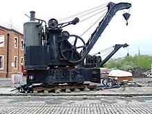
Vertical cross-tube boiler

A cross-tube boiler was the most common form of small vertical boiler. They were widely used, in the age of steam, as a small donkey boiler, for the independent power of winches, steam cranes etc.[1][2][3]
The boiler has the advantage of simple robust construction, in particular requiring little regular maintenance. It is relatively inefficient, which was not a serious drawback to the purposes for which it was used. However it was also of limited heating surface, thus limiting its sustained output power, compared to other boiler designs. For that reason it was rarely used when power was required continuously, such as for locomotives. However as the boiler is of relatively large internal volume relative to its power, this acts as a transient reserve of steam. Applications such as cranes only require steam intermittently, allowing the boiler to recover pressure between lifts.
Construction
[edit]
The boiler consists of a cylindrical vertical external shell, with a large firebox inside this, filling perhaps half of the total height. A single large vertical flue or uptake leads to an external chimney. Some boilers use vertical rod stays between the firebox crown and top of the boiler shell.
The main evaporative surface is provided by a pair of large water-filled cross-tubes across this firebox and directly exposed to the radiant heat of the fire. As these tubes are large in diameter they remain mostly filled with water, rather than filling with steam,[i] and so the boiler is not classed amongst the usual water-tube boilers. These tubes are horizontal,[1] or slightly inclined[2] so as to encourage circulation in a single direction without turbulence.
As usual, there is a manhole in the upper part of the shell for internal access and inspection. The boiler may be distinguished externally from other types of vertical boiler by the additional presence of two smaller handholes, in line with the end of each tube and used for internal cleaning.
Plate and tube wastage in service
[edit]
Unlike fire-tube boilers, the boiler was not designed for regular maintenance; such as the re-tubing and replacement of wasted tubes as a minor event. Any pitting or grooving that did develop would be a major matter to repair, requiring the replacement of plates. In practice, the boilers were robustly constructed and operating at fairly low pressure, and so minor wastage was acceptable.
The most likely location for wastage developing was around the uptake flue, at the operating water level where activity and erosion was most severe.[2] This actually represented one of the boiler's main advantages, compared to vertical boilers with multiple fire-tubes. Erosion there took place on the thin-walled tubes and was a perennial problem.
Improved circulation
[edit]Circulation in boilers is largely due to the thermosyphon effect, which is encouraged by the vertical rise of the water-tubes. As the simple cross-tube boiler has near-horizontal tubes, circulation is poor. To improve this, designs such as the Clarke Chapman 'Tyne' boiler used steeply angled main tubes and small vertical tubes at the sides. This improved circulation, although it made washout difficult.
Notes
[edit]- ^ Large diameter gives a low ratio of heating surface to water volume, thus a low boiling rate.
References
[edit]- ^ a b Prof. William Ripper, Sheffield Univ. d.1937 (1913) [1909]. Heat Engines. Originally published in 1889 as "Steam", but later expanded to cover internal combustion engines and so re-titled. London: Longmans. pp. 196–197.
{{cite book}}: CS1 maint: numeric names: authors list (link) - ^ a b c Milton, J. H. (1961) [1953]. Marine Steam Boilers (2nd ed.). Newnes. pp. 70–77.
- ^ Stokers Manual ((1912 edition) ed.). Admiralty, via HMSO, via Eyre & Spottiswoode. 1901.
External links
[edit]- "New boiler is manufactured for Clyde puffer, VIC 32". Save the Puffer. 2006.
