User:Rudekin/sandbox/Inertial platform
| This is not a Wikipedia article: It is an individual user's work-in-progress page, and may be incomplete and/or unreliable. For guidance on developing this draft, see Wikipedia:So you made a userspace draft. Find sources: Google (books · news · scholar · free images · WP refs) · FENS · JSTOR · TWL |
Inertial platforms are a system that use a gyroscope to stabilize the position of a platform while the vehicle carrying the system moves about. These can be used to stabilize gunsights in aircrafts and as the basis for older navigation systems. In the application of the inertial platform, many problems may arise.
Mechanics
[edit]Gyroscopes
[edit]
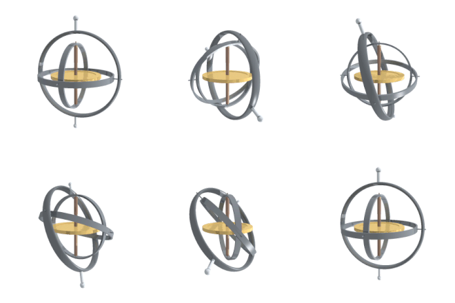
Gyroscopes usually consist of a heavy disk or wheel that spins rapidly about an axis within a mount. A gyroscope being supported by one frame, or gimbal, allows the gyroscope to spin in one axis. With two gimbals, the gyroscope can spin in two axis and with three gimbals the gyroscope can spin in three axis. Having three axis allows the gyroscope any degree of motion.
Gyroscopes also have a special property called rigidity of space. This ability allows the spinning object to stay in the same orientation using inertial space as a reference without any respect to the movement of the frame it is in. This means that as the gimbals rotate and are displaced, gyroscopes always point in the same direction.
Stabilization
[edit]However, if the outermost gimbal is locked into position, only allowing for two degrees of motion, and attached to a platform, the gyroscope could stabilize the stage. For example, the VG120SD is an anti-rolling gyro meant for boats to lessen the effects of ocean waves.[1] Attached at the back of the boat, when a wave would rock the ship from side to side, a torque is applied to the flywheel causing the wheel to tilt, or precess, fore or aft. Precession of the gyroscope creates a torque that opposes the force that was applied by the wave, greatly diminishing the rocking effect and stabilizing the boat.
Applications
[edit]Inertial navigation
[edit]During situations where the pilot has poor visibility or is unsure of their bearings, the attitude indicator allows the pilot to know where the horizon is in relation to the plane. Due to the rigidity of the gyroscope within the attitude indicator, the plane may rotate and move anywhere but the gyroscope will hold the position of the horizon true.[2][3]
Gyro Gunsights
[edit]When attempting to hit a moving target in an aerial battle between aircrafts, the amount of lead that must be given to the shot depends on the rate of turn of the attacking aircraft and the distance from the target. By keeping your cross-hairs on the plane as it turns, sensors on the gimbals of the gyroscope can detect the amount of deflection the gyroscope has gone through and indicate to the pilot how far ahead he must aim.[4]
By adding a gyroscope to the barrel of a tank, this allowed for much greater accuracy of the vehicle and survivability. Instead of having to stop-and-shoot, tanks were able to attack while they stayed on the move.
Problems
[edit]When applying the inertial platform many problems occur that must manually corrected.
Friction
[edit]At each point of contact along the gimbals, friction applies a torque on the gyroscope causing it to deflect 90 degrees from the applied force. Over time, this will cause the gyroscope to drift away from its original position. In order to correct this, sensors are attached onto the gimbals at each axis to detect the deflection of each frame. This data is fed back into a computer and manually adjusted. [6][7]
Schuler Tuning
[edit]As the earth rotates, the vertical axis that is perpendicular to the earth's surface changes along with the rotation. This means that the horizontal axis of the gyroscope must be adjusted constantly. This is known as Schuler Tuning.[8] Found in Maximillian Schuler's 1923 paper, the equation below can be used to find the rate at which torque must be applied.
Ӫ = α/R
Where,
Ӫ = rate at which torque is applied
α = acceleration detected by accelerometers
R = radius of the Earth
Accelerometers (devices that detect acceleration) on the gyroscope will feed their data to torquers on the gimbals and apply the necessary force.
Gimbal lock
[edit]In a system with three gimbals, whenever two or more frames overlap one another, the gyroscope loses access to an axis of rotation. Because of this, when the gyroscope attempts to move into the third axis which it doesn't have, it will not rotate in a straight path. Instead, the gyroscope will flip unnecessarily to regain it's third degree of motion before moving to the correct position. During aerial maneuvers, this can cause inaccurate readings in the attitude indicator and must be manually fixed. This can also be solved by adding a forth gimbal or putting the least used axis of rotation on the outside. For example, if the vertical axis is the least used, the outtermost ring would be frame in charge of vertical movement.
References
[edit]- ^ "How Gyrostabilizers Work - VEEM Gyro". VEEM Gyro. Retrieved 2018-11-03.
- ^ "Gyroscopic Flight Instruments - SKYbrary Aviation Safety". www.skybrary.aero. Retrieved 2018-10-16.
- ^ 2degreewca (2012-11-29), Gyroscopic Instruments - U.S. Navy Aviation Training Film (1960), retrieved 2018-11-04
{{citation}}: CS1 maint: numeric names: authors list (link) - ^ "Charles Stark Draper | American engineer". Encyclopedia Britannica. Retrieved 2018-11-03.
- ^ "Ferranti's Lightweight Inertial Platform". Aircraft Engineering and Aerospace Technology. 36 (11): 356–358. November 1964. doi:10.1108/eb033945. ISSN 0002-2667.
- ^ "Unclassified AD400509" (PDF). Armed Services Technical Information Agency.
- ^ "Characteristics and Stabilization of an Inertial Platform - IEEE Journals & Magazine". ieeexplore.ieee.org. doi:10.1109/TANE3.1958.4201595. S2CID 51657113. Retrieved 2018-10-16.
- ^ imar-navigation.de https://www.imar-navigation.de/downloads/papers/inertial_navigation_introduction.pdf. Retrieved 2018-10-16.
{{cite web}}: Missing or empty|title=(help)
External links
[edit]

