User:HugoBalthazaar/sandbox
Extended IET applications: the Resonalyser Method
[edit]Isotropic versus orthotropic material behaviour
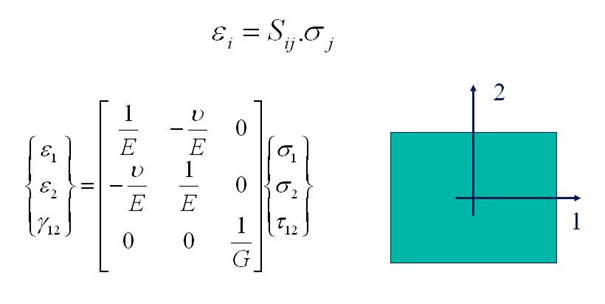
[edit]Isotropic elastic properties can be found by IET using the above described empirical formulas for the Young’s modulus E, the shear modulus G and Poisson’s ratio v. For isotropic materials the relation between strains and stresses in any point of flat sheets is given by the flexibility matrix [S] in the following expression:
In this expression, ε1 and ε2 are normal strains in the 1- and 2-direction and Υ12 is the shear strain. σ1 and σ2 are the normal stresses and τ12 is the shear stress. The orientation of the axes 1 and 2 in the above figure is arbitrary. This means that the values for E, G and v are the same in any material direction.
More complex material behaviour like orthotropic material behaviour can be identified by extended IET procedures. A material is called orthotropic when the elastic properties are symmetric with respect to a rectangular Cartesian system of axes. In case of a two dimensional state of stress, like in thin sheets, the stress-strain relations for orthotropic material become:
E1 and E2 are the Young’s moduli in the 1- and 2-direction and G12 is the in-plane shear modulus. v12 is the major Poisson’s ratio and v21 is the minor Poisson’s ratio. The flexibility matrix [S] is symmetric. The minor Poisson’s ratio can hence be found if E1, E2 and v12 are known.
The figure above shows some examples of common orthotropic materials: layered uni-directionally reinforced composites with fiber directions parallel to the plate edges, layered bi-directionally reinforced composites, short fiber reinforced composites with preference directions (like wooden particle boards), plastics with preference orientation, rolled metal sheets, and much more...
Extended IET for orthotropic material behaviour
[edit]Standard methods for the identification of the two Young’s moduli E1 and E2 require two tensile, bending of IET tests, one on a beam cut along the 1-direction and one on a beam cut along the 2-direction. Major and minor Poisson’s ratios can be identified if also the transverse strains are measured during the tensile tests. The identification of the in-plane shear modulus requires an additional in plane shearing test.
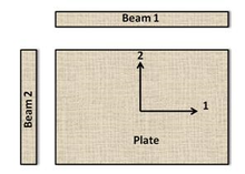
The “Resonalyser procedure”[1][2] [3][4] is an extension of the IET using an inverse method (also called "Mixed numerical experimental method"). The non destructive Resonalyser procedure allows a fast and accurate simultaneous identification of the 4 Engineering constants E1, E2, G12 and v12 for orthotropic materials. For the identification of the four orthotropic material constants, the first three natural frequencies of a rectangular test plate with constant thickness and the first natural frequency of two test beams with rectangular cross section must be measured. One test beam is cut along the longitudinal direction 1, the other one cut along the transversal direction 2 (see Figure on the right).
The Young’s modulus of the test beams can be found using the bending IET formula for test beams with a rectangular cross section.
The ratio Width/Length of the test plate must be cut according to the following formula:
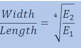
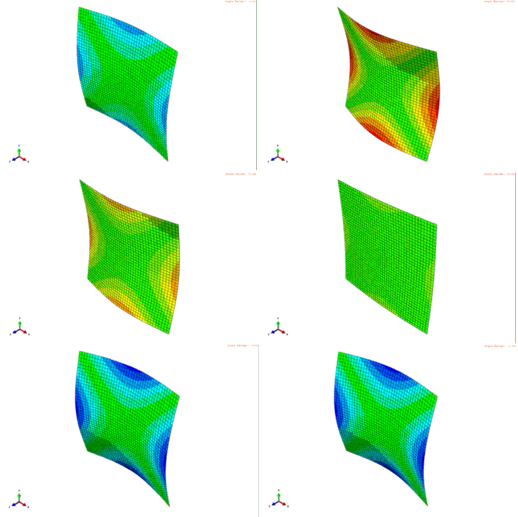
This ratio yields a so-called “Poisson plate”. The interesting property of a Freely suspended Poisson plate is that the modal shapes that are associated with the 3 first resonance frequencies are fixed: the first resonance frequency is associated with a torsional modal shape, the second resonance frequency is associated with a saddle modal shape and the third resonance frequency is associated with a breathing modal shape.
So, without the necessity to do an investigation to the nature of the modal shapes, the IET on a Poisson plate reveals the vibrational behaviour of a Poisson plate.
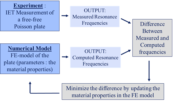
The question is now how to extract the orthotropic Engineering constants from the frequencies measured with IET on the beams and Poisson plate. This problem can be solved by an inverse method (also called" Mixed numerical/experimental method"[5]) based on a finite element (FE) computer model of the Poisson plate. A FE model allows computing resonance frequencies for a given set of material properties
In an inverse method, the material properties in the finite element model are updated in such a way that the computed resonance frequencies match the measured resonance frequencies.
Problems with inverse methods are:
· The need of good starting values for the material properties
· Are the parameters converging to the correct physical solution?
· Is the solution unique?
The requirements to obtain good results are:
- · The FE-model must be sufficiently accurate
- · The IET measurements must be sufficiently accurate
- · The starting values must be close enough to the final solution to avoid a local minimum (instead of a global minimum)
- · The computed frequencies in the FE model of the Poisson plate must be sensitive for variations of all the material parameters
In the case the Young’s moduli (obtained by IET) are fixed (as non variable parameters) in the inverse method procedure and if only the Poisson’s ratio v12 and the in-plane shear modulus G12 are taken as variable parameters in the FE-model, the Resonalyser procedure satisfies all above requirements.
Indeed,
- IET yields very accurate resonance frequencies, even with non-expert equipment,
- a FE of a plate can be made very accurate by selecting a sufficiently fine element grid,
- the knowledge of the modal shapes of a Poisson plate can be used to generate very good starting values using a virtual field method
- and the first 3 natural frequencies of a Poisson plate are sensitive for variations of all the orthotropic Engineering constants.
- ^ Non-destructive testing : proceedings of the First Joint Belgian-Hellenic Conference on Non-Destructive Testing, Patras, Greece, 22-23 May 1995. Hemelrijck, Danny van., Anastassopoulos, Athanassios. Rotterdam: A.A. Balkema. 1996. ISBN 90-5410-595-X. OCLC 35306088.
{{cite book}}: CS1 maint: others (link) - ^ "Theoretical Background of the Resonalyser Procedure".
{{cite web}}: CS1 maint: url-status (link) - ^ T. Lauwagie, H. Sol, G. Roebben, W. Heylen and Y. Shi (2002). "Validation_of_the_Resonalyser_method_an_inverse_method_for_material_identification".
{{cite web}}: CS1 maint: multiple names: authors list (link) CS1 maint: url-status (link) - ^ Lauwagie, Tom; Sol, Hugo; Roebben, Gert; Heylen, Ward; Shi, Yinming; Van der Biest, Omer (2003-10-01). "Mixed numerical–experimental identification of elastic properties of orthotropic metal plates". NDT & E International. 36 (7): 487–495. doi:10.1016/S0963-8695(03)00048-3. ISSN 0963-8695.
- ^ Sol, H. (1997). Material Identification Using Mixed Numerical Experimental Methods : Proceedings of the EUROMECH Colloquium held in Kerkrade, the Netherlands, 7-9 April 1997. Oomens, C. W. J. Dordrecht: Springer Netherlands. ISBN 978-94-009-1471-1. OCLC 851370715.


