User:Chessfan/work1
Chessfan/rewrite Euler angles
[ I will write in brackets explanatory comments directly related to the main text. Less important comments can be found on the discussion page. I would like you to give your comments and suggestions on the discussion page. ]
The Euler angles were developed by Leonhard Euler to describe the orientation of a rigid body (a body in which the relative position of all its points is constant) in 3-dimensional Euclidean space. To describe such an orientation requires exactly three parameters that can be given in several ways, Euler Angles being one of them. This is equivalent to saying that any orientation can be achieved by composing three elemental rotations , and also equivalent to saying that any rotation matrix can be decomposed as a product of three elemental rotation matrices.
Definition

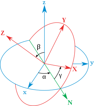
Euler angles are a means of representing the spatial orientation of any frame of reference (coordinate system) as a composition of rotations from a reference frame of reference (coordinate system). In the following the fixed system is denoted in lower case (x,y,z) and the rotated system is denoted in upper case letters (X,Y,Z).
The definition is Static. The intersection of the xy and the XY coordinate planes is called the line of nodes (N). In other words, line of nodes is the line perpendicular to both z and Z axis.
- α (aka ) is the angle between the x-axis and the line of nodes.
- β (aka ) is the angle between the z-axis and the Z-axis.
- γ (aka ) is the angle between the line of nodes and the X-axis.
Euler angles are one of several ways of specifying the relative orientation of two such coordinate systems. Moreover, different authors may use different sets of angles to describe these orientations, or different names for the same angles, leading to different conventions. Therefore any discussion employing Euler angles should always be preceded by their definition.
Unless otherwise stated, this article will use the convention described in the adjacent drawing, usually named Z-X-Z.
Angle signs and ranges
Normally, angles are defined in such a way that they are positive when they rotate counter-clock-wise (how they rotate depends on which side of the rotation plane we observe them from. The positive side will be the one of the positive axis of rotation)
About the ranges:
- α and γ range are defined modulo 2π radians. A valid range could be (-π, π].
- β range covers π radians (but can't be said to be modulo π). For example could be [0, π] or [-π/2, π/2].
The angles α, β and γ are uniquely determined except for the singular case that the xy and the XY planes are identical, the z axis and the Z axis having the same or opposite directions. Indeed, if the z-axis and the Z-axis are the same, β = 0 and only (α+γ) is uniquely defined (not the individual values), and, similarly, if the z-axis and the Z-axis are opposite, β = π and only (α-γ) is uniquely defined (not the individual values). These ambiguities are known as gimbal lock in applications.
Relationship with physical motions
Euler rotations

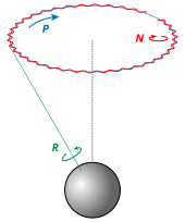
Euler rotations are defined as the movement obtained by changing one of the Euler angles while leaving the other two constant. Euler rotations are never expressed in terms of the external frame, or in terms of the co-moving rotated body frame, but in a mixture. They constitute a mixed axes of rotation system, where the first angle moves the line of nodes around the external axis z, the second rotates around the line of nodes and the third one is an intrinsic rotation around an axis fixed in the body that moves.
These rotations are called Precession, Nutation, and intrinsic rotation.
[Suppress what follows in that section]
Intermediate frames
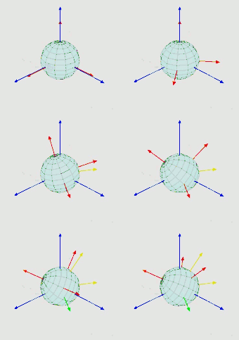
Taking some vectors i, j and k over the axes x, y and z, and vectors I, J, K over X, Y and Z, and a vector N over the line of nodes, some intermediate frames can be defined using the vector cross product, as following:
- origin: [i,j,k] (where k = i x j)
- first: [N,kxN,k]
- second: [N,KxN,K]
- final: [I,J,K]
These intermediate frames are such that they differ from the previous one in just a single elemental rotation. This proves that:
- Any target frame can be reached from the reference frame just composing three rotations.
- The values of these three rotations are exactly the Euler angles of the target frame.
Gimbal analogy
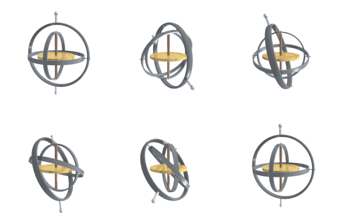
If we suppose a set of frames, able to move each with respect to the former according to just one angle, like a gimbal, there will be one initial, one final and two in the middle, which are called intermediate frames. The two in the middle work as two gimbal rings that allow the last frame to reach any orientation in space.

Conventions
[To be rewritten in relationship with following sections.]
Euler angles in matrix algebra
Let us look at at a specific Euler rotation convention, that is the Z-X-Z convention [ or should we write it Z-X'-Z" ? ].
Representing rotations.
Let us consider a first reference system, or frame, which we name and simple active rotations around each of the three orthonormal basis vectors. Active means that we rotate a vector to a new position . Simple means that we consider only rotations around the basis vectors. When we express for instance a counterclock rotation of positive value around the axis we write, where are column vectors :
The following remarks are useful :
-- We know, which is not true in the general case, the rotation axis by the position (3,3)of the coefficient 1 in the matrix ;
-- but we do not know, unless we indicate it by an index, in which reference frame the matrix is evaluated (that is true also for the vectors) ;
-- we note that the columns of the matrice are the coordinates of the new basis vectors if we transform the old basis by the same rotation. It is useful that we note immediately :
Thus we have also learned how to remember the matrix acting in a passive rotation when switching between two different frames. It is much safer to know how to establish those relations rather than reading them in a table.
The other matrices relevant to the chosen example are :
Combining successive rotations.
Now we rotate both the vector and the frame into the vector and the frame , with the rotation matrix . We must be careful ; we had , now we have !
It should be clear now that we have :
- .............................................
By definition of the second rotation we have also :
and thus :
If now we rotate both the vector and the frame into the vector and the frame , with the rotation matrix we get of course :
Let us take a close look at the following two expressions of :
- represents the fact that we realise the successive rotations around (Euler rotations);
- represents the fact that those rotations are equivalent to the same angular rotations realised around some of the fixed basis vectors (here ), but in the reversed order. That fact may seem surprising, but it is, in the mathematical demonstration, the direct consequence of the simple structure of the matrices : we do not know, without additional information, in which reference frame they act.
Both interpretations are related with the same global active rotation of the body and of course of the final reference frame. In practice the first expression seems more logical, but there is no need to evaluate the matrices ; we evaluate in that order. We might call the first interpretation an intrinsic composition of rotations, and the second one an extrinsic composition of rotations.
The global rotation matrix.
[As could be expected the global rotation matrix is the transpose of the one calculated in the existing matrix section ! By the way that prouves our evaluation is correct.]
If now we want to establish the global rotation matrix for other conventions, we must :
-- be carefull to write the correct matrices ;
-- evaluate .
We must emphasize again that the above matrix describes an active rotation, and is to be multiplicated from the right by a column vector. The columns of that matrix represent the coordinates of the final h-basis vectors in the initial e-basis.
Applications
[References to be reintroduced]

Their main advantage over other orientation descriptions is that they are directly measurable from a gimbal mounted in an aircraft. As gyroscopes keep their rotation axis constant, angles measured in a gyro frame are equivalent to angles measured in the lab frame. Therefore gyros are used to know the actual orientation of moving spacecrafts, and Euler angles are directly measurable. Intrinsic rotation angle cannot be read from a single gimbal, so there has to be more than one gimbal in a spacecraft. Normally there are at least three for redundancy. There is also a relation to the well-known gimbal lock problem of Mechanical Engineering
Euler angles are used extensively in the classical mechanics of rigid bodies, and in the quantum mechanics of angular momentum.
When studying rigid bodies, one calls the xyz system space coordinates, and the XYZ system body coordinates. The space coordinates are treated as unmoving, while the body coordinates are considered embedded in the moving body. Calculations involving kinetic energy are usually easiest in body coordinates, because then the moment of inertia tensor does not change in time. If one also diagonalizes the rigid body's moment of inertia tensor (with nine components, six of which are independent), then one has a set of coordinates (called the principal axes) in which the moment of inertia tensor has only three components. Another perhaps more modern method consists of rotating back the vector in a body copy considered in the space coordinates. is thus an auxiliary vector which permits to write the true angular momentum vector where J is an inertial tensor function of time only through .
The angular velocity, in space coordinates, of a rigid body takes a simple form using Euler angles:
Here the rotation sequence is 3-1-3 (or Z-X-Z using the convention stated above).
The same vector, in body coordinates, is expressed by :
In a mixed coordinate system we have the obvious formula :
In quantum mechanics, explicit descriptions of the representations of SO(3) are very important for calculations, and almost all the work has been done using Euler angles. In the early history of quantum mechanics, when physicists and chemists had a sharply negative reaction towards abstract group theoretic methods (called the Gruppenpest), reliance on Euler angles was also essential for basic theoretical work.
In materials science, crystallographic texture (or preferred orientation) can be described using Euler angles. In texture analysis, the Euler angles provide the necessary mathematical depiction of the orientation of individual crystallites within a polycrystalline material, allowing for the quantitative description of the macroscopic material.
Naval gun fire control systems require corrections to gun-order angles (bearing and elevation) to compensate for deck tilt (pitch and roll). In traditional systems, a stabilizing gyroscope with a vertical spin axis corrects for deck tilt, and stabilizes the optical sights and radar antenna. However, gun barrels point in a direction different from the line of sight to the target, to anticipate target movement and fall of the projectile due to gravity, among other factors. Gun mounts roll and pitch with the deck plane, but also require stabilization. Gun orders include angles computed from the vertical gyro data, and those computations involve Euler angles.
Unit quaternions, also known as Euler-Rodrigues parameters, provide another mechanism for representing 3D rotations.
Expressing rotations in 3D as unit quaternions instead of matrices has some advantages:
- Concatenating rotations is faster and more stable.
- Extracting the angle and axis of rotation is simpler.
- Interpolation is more straightforward. See for example slerp.


_{e}(u)_{e}=(A)_{e}(B)_{f}(u)_{e}=AB(u)_{e}}](https://wikimedia.org/api/rest_v1/media/math/render/svg/5d9285bca2946a68f9944bc0254c6b41fdf332f6)


![{\displaystyle (t)_{e}=[(A)_{e}(B)_{f}(C)_{g}(B)_{f}^{T}(A)_{e}^{T}][(A)_{e}(B)_{f}(A)_{e}^{T}](A)_{e}(u)_{e}=(C)_{e}(B)_{e}(A)_{e}(u)_{e}=(A)_{e}(B)_{f}(C)_{g}(u)_{e}=ABC(u)_{e}}](https://wikimedia.org/api/rest_v1/media/math/render/svg/755930c98670430eab80e47bffad97999826dadc)


