This article is within the scope of WikiProject Physics, a collaborative effort to improve the coverage of Physics on Wikipedia. If you would like to participate, please visit the project page, where you can join the discussion and see a list of open tasks.PhysicsWikipedia:WikiProject PhysicsTemplate:WikiProject Physicsphysics articles
I'm not sure about that new image. It's very nice, but Wikipedia:Profanity seems to say that images that may be objectionable should be used "if and only if their omission would cause the article to be less informative, relevant, or accurate, and no equally suitable alternatives are available." While the image is clearly relevant in that it shows optical caustics, I'm not sure one can argue that its omission would weaken the article, or that no equally suitable images of caustics are available (there being such an image on the article already). Wikipedia is not censored, but that doesn't mean that everything is always appropriate and encyclopedic. --Srleffler19:33, 23 July 2006 (UTC)[reply]
This piqued my curiosity - the image seems to have been a candid topless shot of a woman on a Mexican beach that was spammed to several articles (including sepia). It's been deleted and part of me wonders if the man who took the shot eventually went to prison. It was added to the article by User:H, who is actually User:HighInBC (above); he almost immediately removed it. It appears that User:HighInBC was also an admin, and left Wikipedia a year later after a perception that there had been threats to his family. I wonder which username he uses now? -Ashley Pomeroy (talk) 17:19, 25 April 2014 (UTC)[reply]
If I recall correctly, the image was of a topless woman floating in water, with caustics visible in the water. I don't know anything about the dispute that caused H to leave. As an admin, he was in contact with (and sometimes in dispute with) many other editors, and I don't see any one that stands out as being likely related to the threats.--Srleffler (talk) 04:01, 26 April 2014 (UTC)[reply]
Such concentration of light, especially sunlight, can burn—hence the name.
Something about the ethymology? --Abdull12:27, 5 August 2006 (UTC)[reply]
Yes. The word caustic comes from Greek καυστός, burnt, via the Latin causticus, burning. The article presumes readers are at least familiar with the much more common use of the term caustic to refer to aggressive chemicals like acids that can "burn" exposed skin.--Srleffler16:57, 5 August 2006 (UTC)[reply]
Wolfram says [1]
"The cardioid is a degenerate case of the limaçon. It is also a 1-cusped epicycloid (with r==r) and is the catacaustic formed by rays originating at a point on the circumference of a circle and reflected by the circle." But User:Pne changed it to Nephroid. Which is correct? Both, depending on where the light comes from? Dicklyon17:43, 16 September 2006 (UTC)[reply]
Collett's book claims the locus is a cardioid. Of course it wouldn't be the first error I've found in that book. (Reference on my user page.) Nevertheless, if Pne feels this is correct, he/she needs to provide a reference. Otherwise, it's original research.--Srleffler03:31, 17 September 2006 (UTC)[reply]
The operative bit in the quote you gave is 'rays originating at a point on the circumference of a circle'. Parallel rays instead produce a nephroid; rays from a source in between infinity and the circumference of the circle produce something in between a cardioid and a nephroid. So, by my understanding, the answer to your question 'Both, depending on where the light comes from?' is 'Yes'. See this Mathworld page, for example. -- pne(talk)18:42, 18 September 2006 (UTC)[reply]
I reverted your original replacement of two images yesterday (but not their re-addition today). As I said in my edit summary, I reverted because the images you removed both illustrated specific points discussed in the text—the first shows a caustic with a nephroid shape, which is important in the theory of caustics and is of some mathematical interest. The second image illustrates the simulation of caustics in computer graphics. The images you added are beautiful, but not as valuable to the text of the article as it stands. Pictures on Wikipedia must be more than merely decorative.
I still object to adding both of these images to the article. This is a short article, with a long history of people adding pretty pictures of caustics to it. The article is just not long enough to support everyone's favourite picture of a caustic. My suggestion is that we keep the picture of the fish and caustic, because it does illustrate how caustics can be seen in nature, which is not well represented in the article now. The photo with the eel, on the other hand, does not seem to add sufficient value to the article. It should be removed. I added both images to the collection Caustic (optics) on Wikipedia Commons, however. --Srleffler04:26, 22 September 2007 (UTC)[reply]
Agree.Leave a fish, remove the eel(of course the eel is interesting because the image really shows rainbow colors), but whatever.Thank you.--Mbz104:43, 22 September 2007 (UTC)Mbz1[reply]
Hmm saw this on my watchlist and decided to take a look. This isn't related to Mbz's images but more to the other images on the article. To put it bluntly they're pretty poor. I was a bit disappointed when my two shots: Image:Light through glass05.jpg, Image:Light through glass02.jpg where pulled off. I think they're better than the existing ones. If you disagree I might do a reshoot. --Fir000209:23, 23 September 2007 (UTC)[reply]
I see that it was I who removed your images, although not right after they were added. Other images got added after yours, which I felt were better. I'm not sure what you mean by "poor" here, but let me explain my reasons for preferring the images that are in the article now. This is an article on geometric optics. In this field, one is concerned with the modelling of light as discrete rays, whose propagation through an optical system can be modelled using simple geometrical analysis. As such, I feel that images that display caustics with a simple, clean geometric form best illustrate the optics involved. Your images and Mbz1's are better photographs—more beautiful, more artistic—but they are not better illustrations of the phenomenon that is the subject of this article. --Srleffler17:33, 23 September 2007 (UTC)[reply]
Oh OK - I wasn't really concerned with the artistic side, it's just that the current images are very low res + noisy. And not knowing better and thinking all caustics are much alike and illustrate the point of the article, I felt that my higher quality images would be better suited and useful for users of the encyclopedia. I might try do the same style shots as in the article in higher quality --Fir000222:38, 23 September 2007 (UTC)[reply]
I'm concerned about the paragraph on rainbows. Are rainbows actually considered to be caustics? I would like to see a citation to a source that describes them as such.--Srleffler (talk) 03:16, 20 July 2009 (UTC)[reply]
The most familiar caustic is surely the rainbow, caused by the scattering of light from raindrops in the sky. In brief, the primary rainbow arises from light rays which are twice refracted and once totally internally reflected from a droplet. The scattering angle for these rays can never be less than a certain minimum value. Thus an observer on the ground sees essentially no light above the corresponding direction in the sky. The curve defined in the sky in this way is a directional caustic. Since the index of refraction of water varies slightly with wavelength in the visible, the caustics for different wavelength are formed at slightly different angles, leading to the familiar separation of colors seen in the sky.
I started in on a rewrite of the "Differentiable inverse rendering" section to clean up the incorrect-person and sentence structure issues, but I quickly found myself leaning towards "delete". The first paragraph essentially just repeats the definition of caustic engineering already given in the section above ("Caustic engineering describes the process of solving the inverse problem to computer graphics"), but in a much more wordy way. It then starts into a presentation of one specific technique, based on some conference paper. I'm not sure who the audience for this would be. It is both too technical and too incomplete to be useful. If there is no objection, I'll just delete the whole section in a day or two.--Srleffler (talk) 04:00, 19 January 2020 (UTC)[reply]
@Srleffler: No objections on my part. I agree that the material appears to be presented in a manner that attempted to simplify a complicated technique into a few paragraphs to fit within the article, and in doing so, simplifies it past the point of usefulness. WikiDan61ChatMe!ReadMe!!12:40, 20 January 2020 (UTC)[reply]
I removed the section on pixel art. This seems to be a hypothetical application proposed in one paper. The coverage in the article was undue. The mathematical description given seemed likely to be useful to no one. Also, the first sentence was copied verbatim from the cited source, raising copyright violation questions. --Srleffler (talk) 22:36, 26 January 2020 (UTC)[reply]
I see this has been reinserted as "Per-pixel discrete caustic". As written, this section seems pretty much worthless. The concept is not explained well enough for the section to be useful. At the same time, there is an excess of mathematical detail that doesn't seem to convey anything useful either. Who would benefit from reading this? Further, even if the text were fixed it's a lot of text covering a single very narrow application. The article also does not establish that this is an actual application, as opposed to something hypothetical proposed by somebody in a paper.--Srleffler (talk) 01:50, 29 January 2020 (UTC)[reply]
Many parts of the caustic engineering section are too technical, and just not well enough explained to be useful. The sections delve into the mathematics of how to solve the problem without sufficient explanation. The only readers who will be able to follow this material as it is written are those who already know the subject, and they are unlikely to gain anything from reading it here. Wikipedia is an encylopedia, not a textbook. Material that is this opaque doesn't belong here. Technical material can work, but it has to be clear enough to be useful to somebody.--Srleffler (talk) 03:42, 29 January 2020 (UTC)[reply]
As many complaints above state, the whole paragraph is sub-standard. And WP:OR. I'm bold as Jimbo wants me to and remove it.
The preview seems 1000% more readable already. Pleeeeease don't revert. Thank you.
I'll keep it in here for future reference/discussion:
As the case refraction occurs through a transparent surface, for instance the patterns appearing under clear water surface, 3 main phenomena can be observed:
Very bright (condensed light intensity) points (so-called singularity)
Curve-like objects that connect the points
Regions with low light intensity
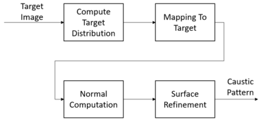
To perform computation, the following 3 quantities are being respectively introduced to describe the geometric characteristics of the pattern: point singularity (measuring light intensity at certain highly concentrated light-point), curve singularity (measuring light intensity at/around a light-curve), and irradiance measure (measuring intensity in a certain poorly concentrated light-area). Putting them altogether, the following function defines the total radiant flux measure at a certain section Ω on the target surface:
After this step, there are two existing measures of the radiant flux measures of the source (uniform distribution, by initialization) and the target (computed in previous step). What remains to compute is the mapping from the source to target. In order to do this, there are several quantities to be defined. Firstly, two light intensities evaluated by probabilities: (light intensity evaluated by dividing by the flux of the union region between and ), (light intensity evaluated by dividing by the flux of the union region between and ) are defined. Secondly, the source mesh is generated as multiple sites , which is later being deformed. Next, a power diagram (a set of power cells) is defined on this set of sites weighted by a weight vector . Finally, the goal is to decide whether which power cells are going to be move. Considering all vertices on the surface, finding the minimizer of the following convex function will produce the matched power diagram for the target:
After solving optimal transport problem, the vertices are achieved. However, this gives no information about what the final surface should look like. To achieve the desired target surface given the incoming light ray , outgoing light ray and power diagram from the step above, the surface normals representation can be computed according to Snell's law as:
: target position obtained from solving above optimal transport problem
As the normal representation is obtained, surface refinement is then achieved by minimizing the following compound energy function:
where,
is the integration energy that aligns the vertex normals obtained from the Optimal Transport with the target normals obtained from the Snell's law computation above.
as mesh generated in step Solving Optimal Transport cannot adapt to the sharp instances from the discontinuities, this energy is to penalize the vertices to not change significantly from the incoming light ray.
is the energy measuring the flux over the triangle in the mesh.
is the energy that regularizes the shape of the triangles to maintain its well-shapedness.
is barrier energy to ensure that surface does not deform beyond a certain distance threshold .
Here considering only refractive caustic, the objective can be determined as follows (similar principle for reflective caustic with different output):
Input: image of pattern to be obtained after propagating lights through the material, given the light source position.
Output: caustic geometry on the receiver (flat solid surface, e.g.: floor, wall, etc...)
In order to achieve the target pattern, the surface where light refracts through and exits to the outer environment must be manufactured into certain shape to achieve desired pattern on the other side of the material.
As mentioned, given an input image, this process will produce the similar caustic pattern as the output. In principle, there are two core stages with each includes two sub-stages:
Optimal-transport-based caustic designSolving Optimal Transport Problem
Compute Target Light Distribution
Compute Mapping from Initial Distribution to Target Distribution
Inverse graphics is a method of observing the data from an image and inferring all possible properties including 3D geometry, lighting, materials, and motion in order to generate a realistic image.[1] In conventional computer graphics, to render an image with desired appearance and effects, it is given all the relevant properties/characteristics. This could be described as the forward method. On the contrary, in caustic design, the properties and characteristics of objects (especially the material surface) are not trivial. The given constraint is the target image to obtain. Therefore, the goal is to obtain its properties and characteristics by observing and inferring the target image. This can be considered the inverse/backward method.
The following is the basic loss function explaining how to optimize the parameters:
where,
L(c): loss function, mean square error of the rendered image and the target
c: contains elements which can influence the generated image
At first, the target pattern is designed and the forward pass computed to get the synthetic pattern. It's compared to the target pattern and get the loss.
The objection is to let the synthetic pattern is similar to the target pattern as much as possible. And then do the back propagation to get the optimized properties need to use in caustic manufacturing.
Introduce U as an intermediate variable indicating 2D projected vertex coordinate positions. The gradient of these properties can be derived by chain rule indirectly.
After applying the stochastic gradient descent, the optimal , and could be achieved. Subsequently, these quantities are used to carve or mill the material to generate the target pattern.
One common approach is to utilize the ability to perform differential operations in various deep learning auto-differentiation frameworks/libraries such as: Tensorflow, PyTorch, Theano.
One more approach is to make use of the OpenDR[1] framework to build a forward graphics model and to automatically obtain derivatives with respect to the model parameters for optimization. As optimization properties are obtained, the target image can be generated. OpenDR provides a local optimization method that can be incorporated into probabilistic programming frameworks. This can be used to solve the problem of caustic. 77.183.64.48 (talk) 06:49, 10 October 2024 (UTC)[reply]
^ abLoper, Matthew M.; Black, Michael J. (2014), "OpenDR: An Approximate Differentiable Renderer", Computer Vision – ECCV 2014, Springer International Publishing, pp. 154–169, doi:10.1007/978-3-319-10584-0_11, ISBN978-3-319-10583-3

.jpg)


![{\displaystyle {\underset {x}{\operatorname {arg\,max} }}\,\omega \,\cdot [E_{int},\,E_{dir},\,E_{flux},\,E_{reg},\,E_{bar}]}](https://wikimedia.org/api/rest_v1/media/math/render/svg/1d94eb1a2815651606db3307362526d05a207426)


