Empennage

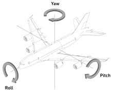
The empennage (/ˌɑːmpɪˈnɑːʒ/ or /ˈɛmpɪnɪdʒ/), also known as the tail or tail assembly, is a structure at the rear of an aircraft that provides stability during flight, in a way similar to the feathers on an arrow.[1][2][3] The term derives from the French language verb empenner which means "to feather an arrow".[4] Most aircraft feature an empennage incorporating vertical and horizontal stabilising surfaces which stabilise the flight dynamics of yaw and pitch,[1][2] as well as housing control surfaces.
In spite of effective control surfaces, many early aircraft that lacked a stabilising empennage were virtually unflyable. Even so-called "tailless aircraft" usually have a tail fin (usually a vertical stabiliser). Heavier-than-air aircraft without any kind of empennage (such as the Northrop B-2) are rare, and generally use specially shaped airfoils whose trailing edge provide pitch stability, and rearwards swept wings, often with dihedral to provide the necessary yaw stability. In some aircraft with swept wings, the airfoil section or angle of incidence may change radically towards the tip.
Structure
[edit]
Structurally, the empennage consists of the entire tail assembly, including the tailfin, the tailplane and the part of the fuselage to which these are attached.[1][2] On an airliner this would be all the flying and control surfaces behind the rear pressure bulkhead.

The front (usually fixed) section of the tailplane is called the horizontal stabiliser and is used to provide pitch stability. The rear section of the tailplane is called the elevator, and is a movable aerofoil that controls changes in pitch, the up-and-down motion of the aircraft's nose. In some aircraft the horizontal stabilizer and elevator are one unit, and to control pitch the entire unit moves as one. This is known as a stabilator or full-flying stabiliser.[1][2]
The vertical tail structure has a fixed front section called the vertical stabiliser, used to control yaw, which is movement of the fuselage right to left motion of the nose of the aircraft. The rear section of the vertical fin is the rudder, a movable aerofoil that is used to turn the aircraft's nose right or left. When used in combination with the ailerons, the result is a banking turn, a coordinated turn, the essential feature of aircraft movement.[1][2]
Some aircraft are fitted with a tail assembly that is hinged to pivot in two axes forward of the fin and stabiliser, in an arrangement referred to as a movable tail. The entire empennage is rotated vertically to actuate the horizontal stabiliser, and sideways to actuate the fin.[5]
The aircraft's cockpit voice recorder, flight data recorder and emergency locator transmitter (ELT) are often located in the empennage, because the aft of the aircraft provides better protection for these in most aircraft crashes.
Trim
[edit]In some aircraft trim devices are provided to eliminate the need for the pilot to maintain constant pressure on the elevator or rudder controls.[5][6]
The trim device may be:
- a trim tab on the rear of the elevators or rudder which act to change the aerodynamic load on the surface. Usually controlled by a cockpit wheel or crank.[5][7]
- an adjustable stabiliser into which the stabiliser may be hinged at its spar and adjustably jacked a few degrees in incidence either up or down. Usually controlled by a cockpit crank.[5][8]
- a bungee trim system which uses a spring to provide an adjustable preload in the controls. Usually controlled by a cockpit lever.[5][6]
- an anti-servo tab used to trim some elevators and stabilators as well as increased control force feel. Usually controlled by a cockpit wheel or crank.[5]
- a servo tab used to move the main control surface, as well as act as a trim tab. Usually controlled by a cockpit wheel or crank.[5]
Multi-engined aircraft often have trim tabs on the rudder to reduce the pilot effort required to keep the aircraft straight in situations of asymmetrical thrust, such as single engine operations.[7]
Tail configurations
[edit]Aircraft empennage designs may be classified broadly according to the fin and tailplane configurations.
The overall shapes of individual tail surfaces (tailplane planforms, fin profiles) are similar to wing planforms.
Tailplanes
[edit]The tailplane comprises the tail-mounted fixed horizontal stabiliser and movable elevator. Besides its planform, it is characterised by:
- Configuration – tailless or canard.
- Location of tailplane – mounted high, mid or low on the fuselage, fin or tail booms.
- Fixed stabiliser and movable elevator surfaces, or a single combined stabilator or "[all]-flying tail".[9] (General Dynamics F-111 Aardvark)
Some locations have been given special names:
- Conventional tail – The vertical stabiliser and horizontal stabilisers are mounted to the rear of the fuselage. This is the simplest configuration that performs all three aspects of the function of a tail: trim, stability, and control.[10] Around 60% of current aircraft designs[10] — and about 80% ever[11] — incorporate this type of tail. Examples are found on aircraft of every size and role, from general aviation types like the ubiquitous Cessna 172 to the largest airliners ever flown, such as the Airbus A380. Examples of this type of tail were in use as early as the Blériot VII of 1907.
- Cruciform tail – The horizontal stabilisers are placed midway up the vertical stabiliser, giving the appearance of a cross when viewed from the front. Cruciform tails are often used to keep the horizontal stabilisers out of the engine wake, while avoiding many of the disadvantages of a T-tail. Examples include the Hawker Sea Hawk and Douglas A-4 Skyhawk.
- T-tail – The horizontal stabiliser is mounted on top of the fin, creating a "T" shape when viewed from the front. T-tails keep the stabilisers out of the engine wake, and give better pitch control. T-tails have a good glide ratio, and are more efficient on low speed aircraft. However, the T-tail has several disadvantages. It is more likely to enter a deep stall, and is more difficult to recover from a spin. For this reason a small secondary stabiliser or tail-let may be fitted lower down where it will be in free air when the aircraft is stalled.[12] A T-tail must be stronger, and therefore heavier than a conventional tail. T-tails also tend to have a larger radar cross section. Examples include the Gloster Javelin and McDonnell Douglas DC-9.
 Fuselage mounted |
 Cruciform |
 T-tail |
 Flying tailplane |
Fins
[edit]The fin comprises the fixed vertical stabiliser and rudder. Besides its profile, it is characterised by:
- Number of fins – usually one or two.
- Location of fins – on the fuselage (over or under), tailplane, tail booms or wings
Twin fins may be mounted at various points:
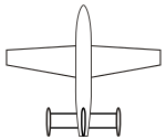
- Twin tail A twin tail, also called an H-tail, consists of two small vertical stabilisers on either side of the horizontal stabiliser. Examples include the Antonov An-225 Mriya, B-25 Mitchell, Avro Lancaster, and ERCO Ercoupe.
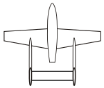
- Twin boom A twin boom has two fuselages or booms, with a vertical stabiliser on each, and a horizontal stabiliser between them. Examples include the Northrop P-61 Black Widow, P-38 Lightning, de Havilland Sea Vixen, Sadler Vampire, and Edgley Optica.
- Wing mounted midwing as on the F7U Cutlass or on the wing tips as on the Handley Page Manx and Rutan Long-EZ
 Tailplane mounted |
 Twin tail boom |
 Wing mounted |
Unusual fin configurations include:
- No fin – as on the McDonnell Douglas X-36. This configuration is sometimes incorrectly referred to as "tailless".
- Multiple fins – examples include the Lockheed Constellation (three), Bellanca 14-13 (three), and the Northrop Grumman E-2 Hawkeye (four).
- Ventral fin – underneath the fuselage. Often used in addition to a conventional fin as on the (North American X-15 and Dornier Do 335).
 Triple fins |
 Ventral fin |
V, Y and X tails
[edit]An alternative to the fin-and-tailplane approach is provided by the V-tail and X-tail designs. Here, the tail surfaces are set at diagonal angles, with each surface contributing to both pitch and yaw. The control surfaces, sometimes called ruddervators, act differentially to provide yaw control (in place of the rudder) and act together to provide pitch control (in place of the elevator).[1]
- V tail: A V-tail can be lighter than a conventional tail in some situations and produce less drag, as on the Fouga Magister trainer, Northrop Grumman RQ-4 Global Hawk RPV and X-37 spacecraft. A V-tail may also have a smaller radar signature. Other aircraft featuring a V-tail include the Beechcraft Model 35 Bonanza, and Davis DA-2. A slight modification to the V-tail can be found on the Waiex and Monnett Moni called a Y-tail.
- Inverted V tail:The unmanned Predator uses an inverted V-tail as do the Lazair and Mini-IMP.
- Y tail: A V-tail with an added lower vertical fin (generally used to protect an aft propeller), as LearAvia Lear Fan
- X tail: The Lockheed XFV featured an "X" tail, which was reinforced and fitted with a wheel on each surface so that the craft could sit on its tail and take off and land vertically.
 V-tail |
 Inverted V-tail |
 X-tail |
Outboard tail
[edit]
An outboard tail is split in two, with each half mounted on a short boom just behind and outboard of each wing tip. It comprises outboard horizontal stabilizers (OHS) and may or may not include additional boom-mounted vertical stabilizers (fins). In this position, the tail surfaces interact constructively with the wingtip vortices and, with careful design, can significantly reduce drag to improve efficiency, without adding unduly to the structural loads on the wing.[13]
The configuration was first developed during World War II by Richard Vogt and George Haag at Blohm & Voss. The Skoda-Kauba SL6 tested the proposed control system in 1944 and, following several design proposals, an order was received for the Blohm & Voss P 215 just weeks before the war ended.[14][15] The outboard tail reappeared on the Scaled Composites SpaceShipOne in 2003 and SpaceShipTwo in 2010.[16]
Tailless aircraft
[edit]
A tailless aircraft (often tail-less) traditionally has all its horizontal control surfaces on its main wing surface. It has no horizontal stabiliser – either tailplane or canard foreplane (nor does it have a second wing in tandem arrangement). A "tailless" type usually still has a vertical stabilising fin (vertical stabiliser) and control surface (rudder). However, NASA adopted the "tailless" description for the novel X-36 research aircraft which has a canard foreplane but no vertical fin.[citation needed]
The most successful tailless configuration has been the tailless delta, especially for combat aircraft.[citation needed]
See also
[edit]References
[edit]- ^ a b c d e f Crane, Dale: Dictionary of Aeronautical Terms, third edition, p. 194. Aviation Supplies & Academics, 1997. ISBN 1-56027-287-2
- ^ a b c d e Aviation Publishers Co. Limited, From the Ground Up, p. 10 (27th revised edition) ISBN 0-9690054-9-0
- ^ Air Transport Association (November 10, 2011). "ATA Airline Handbook Chapter 5: How Aircraft Fly". Archived from the original on November 10, 2011. Retrieved March 5, 2013.
- ^ "Empennage". Oxford Dictionaries Online. Oxford Dictionaries. Archived from the original on July 22, 2012. Retrieved March 5, 2013.
- ^ a b c d e f g Aviation Publishers Co. Limited, From the Ground Up, p. 14 (27th revised edition) ISBN 0-9690054-9-0
- ^ a b Reichmann, Helmet: Flying Sailplanes, p. 26. Thompson Publications, 1980.
- ^ a b Transport Canada: Flight Training Manual 4th Edition, p. 12. Gage Educational Publishing Company, 1994. ISBN 0-7715-5115-0
- ^ Crane, Dale: Dictionary of Aeronautical Terms, third edition, p. 524. Aviation Supplies & Academics, 1997. ISBN 1-56027-287-2
- ^ Anderson, John D., Introduction to Flight, 5th ed, p. 517
- ^ a b Mohammad H. Sadraey, Aircraft Design: A Systems Engineering Approach, Wiley 2013, p.289
- ^ Snorri Gudmundsson, General Aviation Aircraft Design: Applied Methods and Procedures, Elsevier Science 2013, p.483
- ^ Ralph D. Kimberlin, Flight Testing of Fixed Wing Aircraft, AIAA 2003, p.380.
- ^ Kurt W. Muller; "Analysis of a Semi-Tailless Aircraft Design" (Master's thesis), Naval Postgraduate School, US, 2002.[1] Archived November 23, 2022, at the Wayback Machine
- ^ Zdenek Titz and Jaroslav Zazvonil; "Kauba's Dwarfs", Flying Review International, Nov 1965, pp.169-172.
- ^ Pohlmann, Hermann. Chronik Eines Flugzeugwerkes 1932-1945. B&V – Blohm & Voss Hamburg – HFB Hamburger Flugzeugbau (in German). Motor Buch Verlag, 1979 ISBN 3-87943-624-X.
- ^ Benjamin Darrenougue; "Aircraft Configurations With Outboard Horizontal Stabilizers" (Final year project report), Queens University Belfast, 14 May 2004.[2]
