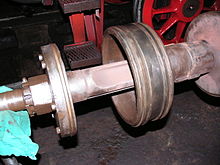
Trofimoff valve

The Trofimoff valve (German: Trofimoff-Schieber) (also Trofimov, Troffimoff or Trofimof) is a springless pressure-compensation piston valve for steam locomotives.
Overview
[edit]The function of the valve is to improve efficiency when running light, with the regulator closed, such as when descending hills.[1] The valve consists of the usual parts of a piston valve: two valve pistons with sealing rings, carried on a valve spindle driven by the valve gear. The difference with a Trofimoff valve is that the piston heads are free to slide on the spindle. When steam pressure is applied, under normal operating conditions, steam is admitted to the centre of the valve chest. This forces the valve heads apart against end stops on the spindle and into their normal working position. The valvegear works as usual.
When the regulator is closed, there is no pressure to force the piston heads apart. The pistons remain stationary in the centre of their travel, uncovering the valve ports. There is now a clear path through the valves and the working pistons, allowing free running for the coasting locomotive.[1]
Origins
[edit]The origins of this type of piston valve are not precisely known. It was probably developed in the 1920s in Germany, but its patents seem to have gone at that time to the Soviet State Railway. Other sources speak of it being developed by Bulgarian railway engineers. Russian sources claim that the valve was invented in 1908 by a Moscow Sorting Station service technician I.Trofimov (or Trofimoff, thus the name), but the Russian Revolution and Civil War slowed adoption, so the design gradually spread on the word-of-mouth, and was patented only in the 1920s.
Operation
[edit]

The Trofimoff valve comprises the valve spindle, the piston valve heads slotted onto them and the two supporting plates (Stützplatten). When the engine is running under load the valve heads are forced by steam pressure onto the support plates and work like standard pistons (Regelkolbenschieber). If steam admission ceases or, on a steam locomotive, the regulator is closed, the pressure drops, the valve heads remain in the inside dead centre position near the centre of the cylinder due to the tension of the piston rings. The valve spindle continues to move backwards and forwards with the support plates attached to it, without disturbing the valve heads. In this way, perfect pressure balance is achieved, thus ensuring excellent light-running conditions for the steam engine or locomotive.
The support plates fixed to the valve spindle also have a piston ring. This slows down the closing of the movable valve heads. Narrow gauge locomotives (such as the DR Class 99.23–24) do not have these piston rings. As a result, when the locomotive switches from running light to running under load there is a characteristic clicking noise as the pistons close. This piston ring on the support body was a further refinement by the former Meiningen repair shop.
So that the entire locomotive cylinder block does not have to be changed when the valves are damaged, they are housed in special chests. The valve chest consists of two elements which are forced into the cylinder block from the front and rear. Using special boring tools this chest can be bored out several times during maintenance. In the last illustration the junction of the two halves of the chest and the right-angled ports can be seen towards the rear. These are steam admission ports. Steam is admitted to the pistons of the steam engine through the front diagonal slits. The front area, outside the valve chest, is called the exhaust chest and discharges, via the exhaust pipe, the riser (Standrohr) and the blast pipe cap (Blasrohrkopf) centrally, underneath the chimney of the locomotive.
The motion of the valve heads alternately opens and closes the diagonal slits or steam ports, thus controlling the admission and exhausting of steam in the steam engine.
References
[edit]- ^ a b Bell, A. Morton (1948). Locomotives: Their Construction, Maintenance and Operation. Vol. One (Sixth ed.). Virtue & Company. pp. 70–71.
