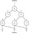
File:Three input Boolean circuit.jpg
Appearance

Size of this preview: 676 × 600 pixels. Other resolutions: 271 × 240 pixels | 541 × 480 pixels | 866 × 768 pixels | 1,038 × 921 pixels.
Original file (1,038 × 921 pixels, file size: 54 KB, MIME type: image/jpeg)
Summary
[edit]| Description |
Three input Boolean circuit diagram with example inputs and output |
|---|---|
| Source |
Created in Latex with TikZ package |
| Date |
2020-04-07 |
| Author | |
| Permission (Reusing this file) |
See below.
|
| A vector version of this image is also available, and should be used in place of this raster image where the raster image contains information that could be stored more efficiently and/or accurately in the SVG format, as a vector graphic.
If its license requires the preservation of attribution or revision history, the raster version of this image should not be deleted, in order to maintain this information. For more information, see the documentation on MediaWiki's support of SVG images. |  |
Licensing
[edit]I, the copyright holder of this work, hereby publish it under the following licenses:
 | Permission is granted to copy, distribute and/or modify this document under the terms of the GNU Free Documentation License, Version 1.2 or any later version published by the Free Software Foundation; with no Invariant Sections, no Front-Cover Texts, and no Back-Cover Texts. |
| This work is licensed under the Creative Commons Attribution-ShareAlike 4.0 License. |
You may select the license of your choice.
File history
Click on a date/time to view the file as it appeared at that time.
| Date/Time | Thumbnail | Dimensions | User | Comment | |
|---|---|---|---|---|---|
| current | 22:16, 7 April 2020 |  | 1,038 × 921 (54 KB) | Jaydavidmartin (talk | contribs) | Uploading a self-made file using File Upload Wizard |
You cannot overwrite this file.
File usage
The following 5 pages use this file:
