Jump to content

File:Dipole receiving antenna animation 6 800x394x150ms.gif

Page contents not supported in other languages.
This is a file from the Wikimedia Commons
From Wikipedia, the free encyclopedia

Dipole_receiving_antenna_animation_6_800x394x150ms.gif (800 × 394 pixels, file size: 271 KB, MIME type: image/gif, looped, 16 frames, 2.4 s)

Summary

Description
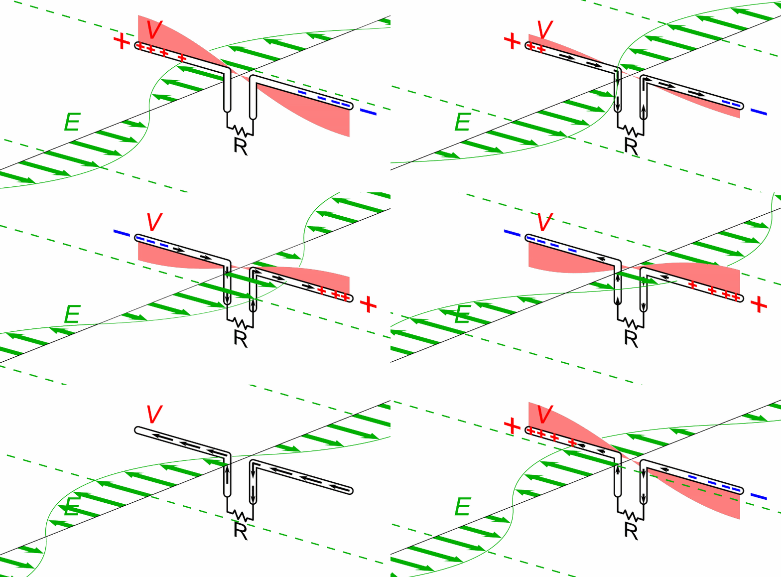
English: Animation showing a half-wave dipole antenna receiving power from a radio wave. The antenna consists of two metal rods each one-quarter of the wavelength long, attached through a parallel transmission line to a resistance R equal to the characteristic impedance of the antenna, representing the receiver. The electromagnetic wave is represented by its electric field (E, green arrows) (it should be kept in mind that the drawing only shows the field along one line, while the radio wave is actually a plane wave and the electric field is actually the same at every point on a plane perpendicular to the direction of motion). The wave's magnetic field is not shown.

The oscillating electric field exerts force on the electrons in the antenna rods , causing them to move back and forth in currents (black arrows) between the ends of the antenna rods, charging the ends of the antenna alternately positive (+) and negative (−). Since the antenna is a half-wavelength long at the radio wave's frequency, it excites standing waves of voltage (V, red) and current in the antenna. The voltage along the antenna elements is represented graphically by a band of red whose thickness at any point is proportional to the magnitude of the voltage. The oscillating currents flowing back and forth from one antenna element to the other, pass down the transmission line and through the radio receiver, represented by R. In this animation the action is shown slowed down drastically; the radio waves received by dipoles actually oscillate back and forth at tens of thousands to billions of cycles per second.
Date
Source Own work
Author Chetvorno
Other versions

Dipole receiving antenna animation 6 300ms.gif Slower version
Dipole receiving antenna animation 2 800x403x15ms.gif - more wide view

Dipole_receiving_antenna_animation_4_616x380x150ms.gif - shows waves of voltage and current traveling down transmission line
This circuit image could be re-created using vector graphics as an SVG file. This has several advantages; see Commons:Media for cleanup for more information. If an SVG form of this image is available, please upload it and afterwards replace this template with {{vector version available|new image name}}. It is recommended to name the SVG file "Dipole receiving antenna animation 6 800x394x150ms.svg" - then the template Vector version available (or Vva) does not need the new image name parameter.

Licensing

I, the copyright holder of this work, hereby publish it under the following license:
Creative Commons CC-Zero This file is made available under the Creative Commons CC0 1.0 Universal Public Domain Dedication.
The person who associated a work with this deed has dedicated the work to the public domain by waiving all of their rights to the work worldwide under copyright law, including all related and neighboring rights, to the extent allowed by law. You can copy, modify, distribute and perform the work, even for commercial purposes, all without asking permission.

Captions

Animated diagram of a dipole antenna receiving radio waves

Items portrayed in this file

depicts

7 June 2015

File history

Click on a date/time to view the file as it appeared at that time.

Date/TimeThumbnailDimensionsUserComment
current07:47, 7 June 2015Thumbnail for version as of 07:47, 7 June 2015800 × 394 (271 KB)ChetvornoUser created page with UploadWizard

Global file usage

The following other wikis use this file:

View more global usage of this file.

Metadata