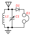
File:Common crystal radio circuit.svg
Appearance

Size of this PNG preview of this SVG file: 517 × 426 pixels. Other resolutions: 291 × 240 pixels | 583 × 480 pixels | 932 × 768 pixels | 1,243 × 1,024 pixels | 2,486 × 2,048 pixels.
Original file (SVG file, nominally 517 × 426 pixels, file size: 23 KB)
File history
Click on a date/time to view the file as it appeared at that time.
| Date/Time | Thumbnail | Dimensions | User | Comment | |
|---|---|---|---|---|---|
| current | 20:03, 19 July 2018 |  | 517 × 426 (23 KB) | Chetvorno | Improved placement of parts, simplified labels, added label for antenna |
| 02:42, 28 January 2016 |  | 517 × 426 (33 KB) | Chetvorno | Increased line width and tweaked location of antenna and ground | |
| 21:54, 9 June 2010 |  | 364 × 426 (28 KB) | Chetvorno | Replaced circuit diagram with identical one lacking blocking capacitor | |
| 04:30, 21 May 2010 |  | 517 × 426 (34 KB) | Chetvorno | {{Information |Description={{en|Common Wikipedia:crystal radio circuit, used in educational crystal radios sold today. The tuned circuit ''L1'', ''C1'' is tuned to different stations by a variable capacitor. The crystal detector ''D1'' rectifies the |
File usage
The following 2 pages use this file:
Global file usage
The following other wikis use this file:
- Usage on no.wikipedia.org
- Usage on zh.wikipedia.org
