DIN 41612


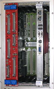
DIN 41612 was a DIN standard for electrical connectors that are widely used in rack based electrical systems. Standardisation of the connectors is a pre-requisite for open systems, where users expect components from different suppliers to operate together. The most widely known use of DIN 41612 connectors is in the VMEbus and NuBus systems. The standard has withdrawn in favor of international standards IEC 60603-2 and EN 60603-2.
DIN 41612 connectors are used in Pancon,[1] STEbus,[2] Futurebus, VMEbus, Multibus II, NuBus, Acorn Archimedes expansion bus,[3] VXI Bus,[4] eurocard TRAM motherboards,[5] and Europe Card Bus, all of which typically use male DIN 41612 connectors on Eurocards plugged into female DIN 41612 on the backplane in a 19-inch rack chassis.
Normal and Reversed connectors
[edit]To support the plug-in card/backplane configuration, the "normal" versions of these connectors have right-angle PCB mounting pins on the male DIN 41612 connector and straight PCB mounting pins on the female DIN 41612 connector.
There also exist "Reversed" connectors, in which the male DIN 41612 connector has straight mounting pins and the female DIN 41612 connector has right-angle mounting pins.
The pin numbering of the connectors is such that, if a "normal" connector is replaced with a "Reversed" connector, the row ordering and the pin numbering is unchanged: what was male pin a1 is now female receptacle a1. As a result, if two boards are designed to connect edge-to-edge with no backplane, one board would require a "normal" connector (male with right-angle pins) and the other would require a "Reversed" connector (female with right-angle pins). In this arrangement, the row ordering is unchanged but the pin ordering is mirrored: male pin a1 is connected to female receptacle a32.
Failure to appreciate this numbering subtlety led to multiple instances where prototype circuit boards had "mirror imaged" connections to their connectors: an expensive and embarrassing mistake[citation needed] (but at least one in which the circuit designer and the layout engineer could each blame the other).
Mechanical details
[edit]The standard describes connectors which may have one, two or three rows of contacts, which are labelled as rows a, b and c. Two row connectors may use rows a+b or rows a+c. The connectors may have 16 or 32 columns, which means that the possible permutations allow 16, 32, 48, 64 or 96 contacts. The rows and columns are on a 0.1 inch (2.54 mm) grid pitch. Insertion and removal force are controlled, and three durability grades are available.
Often the female DIN 41612 connectors have press fit contacts rather than solder pin contacts, to avoid thermal shock to the backplane.[6]
Electrical details
[edit]The headline performance of the connectors is a 2 amp per pin current carrying capacity, and 500 volt working voltage. Both these figures may need to be de-rated according to safety requirements or environmental conditions.
Performance Classes
[edit]The DIN 41612 specification identifies 3 different classes or "levels": class 1 is rated for 500 mating cycles, class 2 for 400 mating cycles, and class 3 for 50 mating cycles.
References
[edit]- ^ DIN 41612
- ^ Michael J. Spinks. "Microprocessor System Design: A Practical Introduction". 2013. p. 158.
- ^ Acorn Enhanced Expansion Card Specification (formerly Acorn expansion card specification) (PDF) (5 ed.). Acorn Computers Ltd. 1994.
- ^ "Eurocard Connectors per DIN 41612 and IEC 60603-2"
- ^ "IMS B012 User Guide and Reference Manual". "Appendix A". 1988.
- ^ Andrew Fletcher. "Connector Industry: A Profile of the European Connector Industry". p. 67.
External links
[edit]
