Color calibration
This article needs additional citations for verification. (October 2023) |
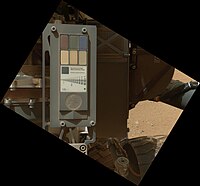
The aim of color calibration is to measure and/or adjust the color response of a device (input or output) to a known state.[1] In International Color Consortium (ICC) terms, this is the basis for an additional color characterization of the device and later profiling.[2] In non-ICC workflows, calibration sometimes refers to establishing a known relationship to a standard color space[3] in one go. The device that is to be calibrated is sometimes known as a calibration source; the color space that serves as a standard is sometimes known as a calibration target.[citation needed] Color calibration is a requirement for all devices taking an active part in a color-managed workflow and is used by many industries, such as television production, gaming, photography, engineering, chemistry, medicine, and more.
Information flow and output distortion
[edit]Input data can come from device sources like digital cameras, image scanners, or any other measuring devices. Those inputs can be either monochrome (in which case only the response curve needs to be calibrated, though in a few select cases, one must also specify the color or spectral power distribution that that single channel corresponds to) or specified in multidimensional color, most commonly in the three-channel red-green-blue model. Input data is, in most cases, calibrated against a profile connection space (PCS).[4]
One of the most important factors to consider when dealing with color calibration is having a valid source. If the color measuring source does not match the display's capabilities, the calibration will be ineffective and give false readings.
The main distorting factors on the input stage stem from the amplitude nonlinearity of the channel responses, and in the case of a multidimensional datastream, the non-ideal wavelength responses of the individual color separation filters, most commonly a color filter array, in combination with the spectral power distribution of the scene illumination.
After this, the data is often circulated in the system and translated into a working space RGB for viewing and editing.
In the output stage, when exporting to a viewing device such as a cathode ray tube, liquid crystal display screen, or digital projector, the computer sends a signal to the computer's graphic card in the form of RGB [Red, Green, Blue]. The dataset [255,0,0] signals only a device instruction, not a specific color. This instruction [R,G,B]=[255,0,0] then causes the connected display to show Red at the maximum achievable brightness [255], while the Green and Blue components of the display remain dark [0]. The resultant color being displayed, however, depends on two main factors:
- the phosphors or another system actually producing a light that falls inside the red spectrum;
- the overall brightness of the color, resulting in the desired color perception: an extremely bright light source will always be seen as white, irrespective of spectral composition.
Hence, every output device will have its own unique color signature, displaying a certain color according to manufacturing tolerances and material deterioration through use and age. If the output device is a printer, additional distorting factors are the qualities of a particular batch of paper and ink.
The conductive qualities and standards-compliance of connecting cables, circuitry, and equipment can also alter the electrical signal at any stage in the signal flow. (A partially inserted VGA connector can result in a monochrome display, for example, as some pins are not connected.)
Color perception
[edit]
Color perception is subject to ambient light levels, and the ambient white point; for example, a red object looks black in blue light. It is therefore not possible to achieve calibration that will make a device look correct and consistent in all capture or viewing conditions. The computer display and calibration target will have to be considered in controlled, predefined lighting conditions.
Calibration techniques and procedures
[edit]
The most common form of calibration aims at adjusting cameras, scanners, monitors, and printers for photographic reproduction. The aim is that a printed copy of a photograph appears identical in saturation and dynamic range to the original or a source file on a computer display. This means that three independent calibrations need to be performed:
- The camera or scanner needs a device-specific calibration to represent the original's estimated colors in an unambiguous way.
- The computer display needs a device-specific calibration to reproduce the colors of the image color space.
- The printer needs a device-specific calibration to reproduce the colors of the image color space.
These goals can either be realized via direct value translation from source to target, or by using a common known reference color space as middle ground. In the most commonly used color profile system, ICC, this is known as the PCS or "Profile Connection Space".
Camera
[edit]The camera calibration needs a known calibration target to be photographed and the resulting output from the camera to be converted to color values. A correction profile can then be built using the difference between the camera result values and the known reference values. When two or more cameras need to be calibrated relatively to each other, to reproduce the same color values, the technique of color mapping can be used.
Scanner
[edit]
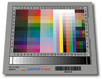
For creating a scanner profile it needs a target source, such as an IT8-target, an original with many small color fields, which was measured by the developer with a photometer. The scanner reads this original and compares the scanned color values with the target's reference values. Taking the differences of these values into account an ICC profile is created, which relates the device-specific color space (RGB color space) to a device-independent color space (L*a*b* color space). Thus, the scanner is able to output with color fidelity to what it reads.
Display
[edit]
For calibrating the monitor a colorimeter is attached flat to the display's surface, shielded from all ambient light. The calibration software sends a series of color signals to the display and compares the values that were actually sent against the readings from the calibration device. This establishes the current offsets in color display. Depending on the calibration software and type of monitor used, the software either creates a correction matrix (i.e. an ICC profile) for color values before being sent to the display or gives instructions for altering the display's brightness/contrast and RGB values through the OSD. This tunes the display to reproduce fairly accurately the in-gamut part of a desired color space. The calibration target for this kind of calibration is that of print stock paper illuminated by D65 light at 120 cd/m2.
Printer
[edit]The ICC profile for a printer is created by comparing a test print result using a photometer with the original reference file. The test chart contains known CMYK colors, whose offsets to their actual L*a*b* colors scanned by the photometer result in an ICC profile. Another possibility to ICC profile a printer is to use a calibrated scanner as the measuring device for the printed CMYK test chart instead of a photometer. A calibration profile is necessary for each printer/paper/ink combination.
See also
[edit]References
[edit]- ^ Wransky, Michael (November 3, 2015). Color Calibration Techniques for True Color Measurement: Computer Interpretation of Color. Lap Lambert Academic Publishing GmbH KG. ISBN 978-3-659-78939-7.
- ^ Graeme Gill. "Calibration vs. Characterization". Graeme Gill. Archived from the original on October 30, 2011. Retrieved November 4, 2011.
- ^ Hsien-Che Lee (2005). Introduction to color imaging science. Cambridge University Press. ISBN 0-521-84388-X.
- ^ Ann L. McCarthy. "Color Imaging Workflow Primitives" (PDF). International Color Consortium. Archived (PDF) from the original on July 31, 2021. Retrieved September 14, 2021.

